![]()
PL-LAB basic experiment tutorial
This tutorial will guide you through the process of specifying topology, reserving resources and executing a simple experiment using PL-LAB facility resources.
You will use the jFed experimenter GUI to run the experiment.
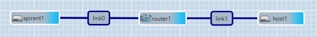
The experiment network will consist of three types of resources offered by PL-LAB: Spirent traffic generator, Juniper router and a server. In this exemplary scenario, you’ll generate UDP traffic on one of the Spirent interfaces connected to the router. This traffic will be received on one of the router interfaces, processed with a policer and sent further on another interface towards a server on which it will be visualized.
Create Fed4FIRE account and obtain credentials
In case you don’t have a Fed4FIRE account yet please refer to How to get access to PL-LAB resources? section on the HOWTO page.
Download and run jFed experimenter GUI
In case you’re not familiar with jFed please refer to How to run experiments in PL-LAB? Section on the HOWTO page.
Load experiment specification
Download the template RSpec file with the basic experiment setup from here.
Use the Open button from the jFed’s top bar menu to load the file with experiment topology.
Alternatively, you can build the required topology manually using the jFed’s graphical editor.
Run the experiment
Use the Run button from the jFed’s top bar menu, fill in the required data (experiment name, project and duration) and start the experiment to provision the specified resources.
The requested experiment duration must not exceed 3 hours since this is the default maximal allowed value. In order to increase the limit please contact PL-LAB admins by email to pllab-fed4fire-admin@lists.man.poznan.pl.
Once the experiment network provisioning process is finished, you can log on the requested resources using SSH and enter a simple configuration in order to validate proper setup of the network. In the case of router1 and host1 resources, you can log on the device by double-click on the node icon which will open a new Putty session window.
Log on the host1 (server) and enter the following shell commands to set appropriate address on the eth1 interface and start monitoring the received traffic:
sudo ip addr add 192.168.100.1/24 dev eth1
sudo ip link set dev eth1 up
sudo route add -net 192.168.50.0/24 gw 192.168.100.2 dev eth1
sudo speedometer -r eth1 -l -m 40000000
Log on the router1 and enter the following set of commands in the CLI in order to setup simple connectivity:
configure
set interfaces ge-2/0/0 unit 0 family inet address 192.168.50.2/24
set interfaces ge-2/0/1 unit 0 family inet address 192.168.100.2/24
Once the basic connectivity between Spirent generator and the host is confirmed you can use router features to influence the traffic characteristics and observe the results.
For guidelines on how to connect to Spirent GUI please refer to How to setup simple experiment with PL-LAB Spirent traffic generator? section on the HOWTO page.
Once the additional SSH tunnels are configured you may proceed in two ways, either load existing configuration file that you can download here and start generating traffic as in step 9 or follow these steps to start generating UDP traffic towards host1.
1) Open Spirent TestCenter Application
2) Close the „Welcome to Spirent TestCenter” window if it shows
3) Go to Actions->Chassis->Port_Reservation
4) Click on „Add Chassis…” and enter chassis IP address „127.0.0.1”
3) After successful connection to chassis select appropriate ports (physical ports of Spirent Chassis that you want to use in your experiment) and click on „OK” button
4) In the left pane select Spirent_TestCenter->Ports->Port //1/1->Traffic Generator
5) In the right pane clink on Add->Add_Raw_Stream_Block
6) In the „Stream Block Properties” perform the following and after you should see the configured streamblock
6.1) In „General” tab set size of generated frames
6.2) In „Frame” tab set Destination MAC to 28:C0:DA:06:5D:2A
6.3) In „Frame” tab set IP addresses: Source to 192.168.50.1, Destination to 192.168.100.1 and Gateway to 192.168.50.2
6.4) In „Frame” tab add UDP header by clicking on „Add Header” and selecting UDP
6.5) Click on „OK” buton
7) Change the scheduling mode from port based to load per steamblock
8) In the steamblock definition change load units to Mbps and set load to 30Mbps
9) Right-click on the streamblock and select „Start” to start traffic generation.
Now you should be able to see the traffic volume received on the host1.